Common Challenges in Coupling Procurement
Understanding your critical concerns helps us deliver solutions that eliminate costly downtime and ensure precision performance
Unstable Torque Transfer
Inconsistent torque transmission creates dangerous vibrations that damage your precision machinery, reduce operational lifespan, and compromise product quality in every production cycle.
Shaft Diameter Mismatch
Standard couplings rarely fit diverse equipment specifications, causing frustrating installation delays, requiring expensive custom adaptors, and forcing engineers to compromise on system performance.
Poor Material Quality
Low-grade materials lead to frequent coupling failures, unexpected production shutdowns, emergency replacement costs, and mounting maintenance expenses that destroy your budget forecasts.
High-Speed Noise Issues
Excessive noise at elevated RPM indicates poor coupling balance and misalignment, degrading overall machine accuracy, creating workplace safety concerns, and signaling imminent mechanical failure.
Unreliable Supply Chain
Unpredictable delivery schedules halt production lines, force costly inventory stockpiling, strain customer relationships, and create emergency sourcing situations that multiply procurement costs significantly.
Inconsistent Manufacturing Tolerance
Variable production quality generates assembly difficulties, post-installation misalignment problems, accelerated wear patterns, and performance deviations that undermine your equipment's precision capabilities completely.
Stop losing productivity to unreliable couplings
Discover Our SolutionsWhy Leading Manufacturers Trust Our Coupling Solutions
Combining engineering expertise with precision manufacturing to deliver couplings that enhance your equipment performance and operational reliability
Expert Engineering Team
Our mechanical engineers understand transmission system dynamics deeply, providing technical consultation that ensures optimal coupling selection for your specific application requirements and performance goals.
Advanced CNC Manufacturing
State-of-the-art precision machining centers maintain tolerances within ±0.01mm, guaranteeing perfect concentricity, balanced rotation, and consistent quality across every coupling unit we produce for your operations.
Custom Shaft Adaptation
Flexible customization accommodates non-standard shaft diameters, keyway configurations, and special mounting requirements, eliminating installation headaches and ensuring seamless integration with your existing equipment portfolio.
Multi-Industry Compatibility
Proven performance across CNC machining centers, industrial robotics, and automated assembly systems demonstrates versatile application engineering that addresses diverse mechanical transmission challenges in modern manufacturing environments.
Stable Supply Capacity
Established production infrastructure and inventory management systems ensure consistent delivery schedules, preventing production disruptions and enabling confident long-term planning for your manufacturing operations.
Pre-Sales Technical Support
Comprehensive selection assistance includes torque calculations, misalignment analysis, and application-specific recommendations before purchase, minimizing specification errors and accelerating your equipment commissioning process.
Experience precision engineering that transforms your mechanical transmission reliability
Request Technical ConsultationBest-Selling Precision Coupling Solutions
Engineered for reliability, manufactured for precision - our most trusted coupling models deliver consistent performance across diverse industrial applications
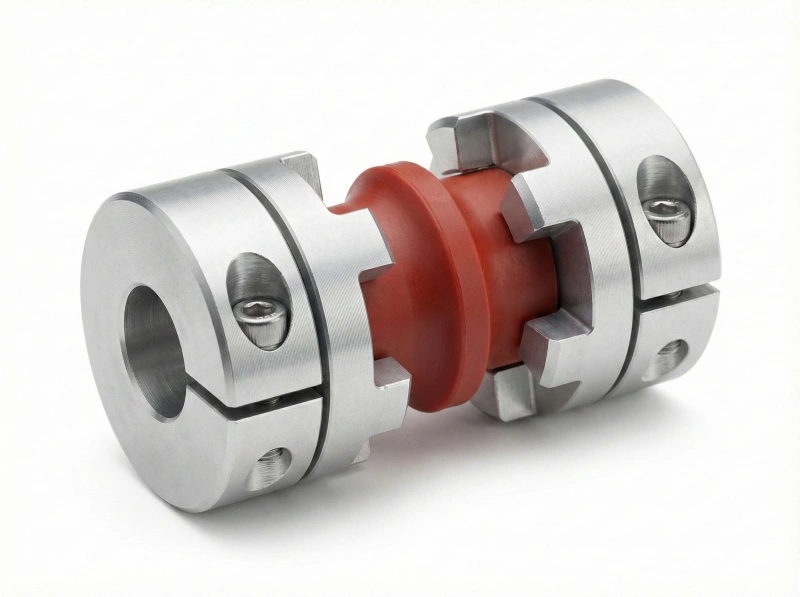
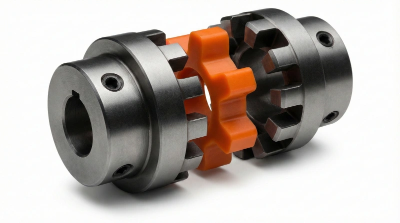
Plum Coupling
Flexible jaw design with plum-shaped elastomer insert absorbs vibrations while maintaining high torque capacity for servo motor applications.
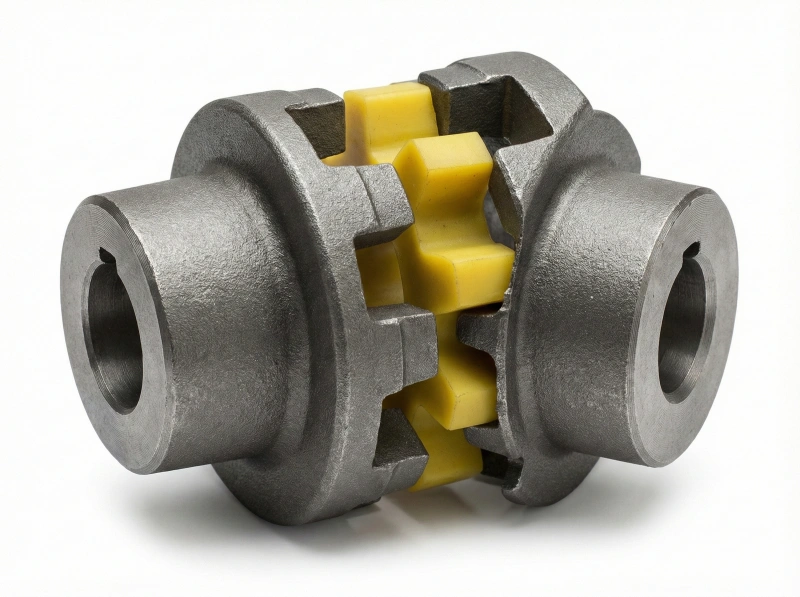
Jaw Coupling
Three-piece construction provides excellent misalignment tolerance and electrical isolation, perfect for pump and conveyor drive systems.
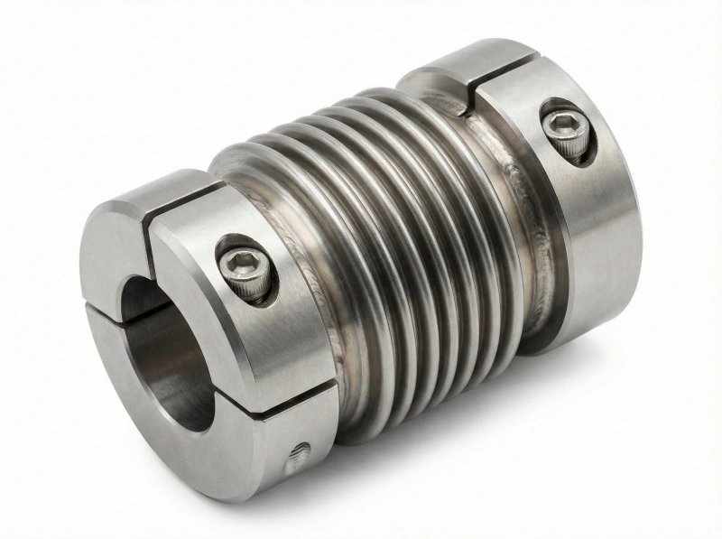
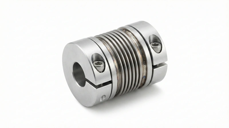
Flexible Bellows Coupling
Stainless steel bellows construction delivers zero backlash performance with exceptional torsional rigidity for CNC and robotic applications.
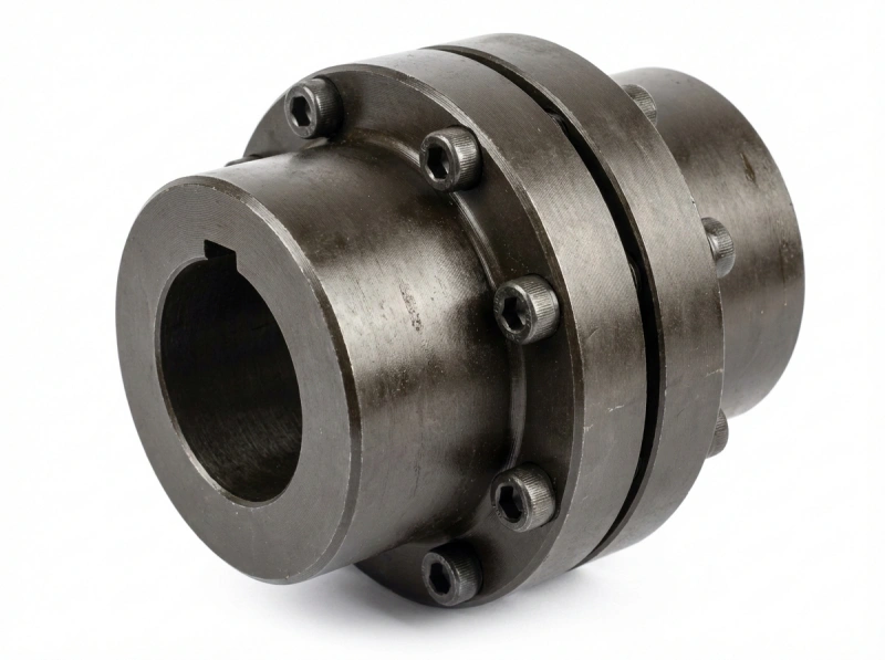
Rigid Coupling
Solid one-piece or two-piece design transmits maximum torque without flexibility, ideal for precisely aligned heavy-duty applications.
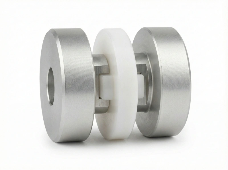
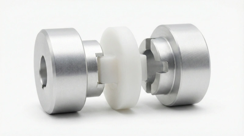
Oldham Coupling
Three-disc design with sliding center element compensates parallel offset while maintaining constant velocity output for motion control systems.
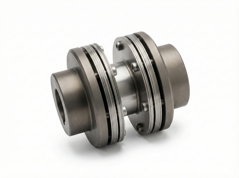
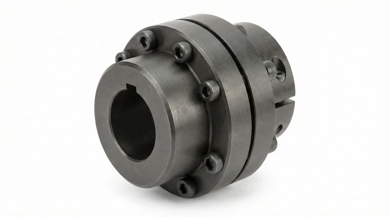
High-Torque Disc Coupling
Multiple metallic disc packs provide ultra-high torque capacity with low inertia, engineered for demanding industrial machinery and power transmission.
Need help selecting the right coupling for your application?
Consult Our EngineersTechnical Specifications
Detailed dimensional and performance parameters for precise system integration
| Type | Dimensions | |||||||
|---|---|---|---|---|---|---|---|---|
| D1 D2 | D | L | L1 | L2 | S | L3 | M | |
| DLK8-C14 | 2/3/4/5/6/7 | 14 | 22 | 7 | 6 | 1 | 3.5 | M2.5 |
| DLK8-C20 | 4/5/6/6.35 | 20 | 30 | 10 | 8 | 1 | 5 | M3 |
| DLK8-C25 | 4/5/6/6.35 8/10/11/12 |
25 | 34 | 11 | 10 | 1 | 5 | M4 |
| DLK8-C30 | 8/9.55/10 12/14/16 |
30 | 35 | 11 | 10 | 1.5 | 5 | M4 |
| DLK8-C40S | 14/16/19 20/22/24 |
40 | 55 | 19.5 | 12 | 2 | 10 | M6 |
| DLK8-C40 | 14/16/18/19 20/22/24 |
40 | 66 | 25 | 12 | 2 | 10 | M6 |
| DLK8-C55 | 14/16/19 24/25/28 |
55 | 78 | 30 | 14 | 2 | 10 | M6 |
| DLK8-C65 | 19/20/24/28 30/35/38 |
65 | 90 | 35 | 15 | 2.5 | 15 | M8 |
| DLK8-C80 | 24/28/30/35 38/40/45 |
80 | 114 | 45 | 18 | 3 | 15 | M8 |
| DLK8-C95 | 30/35/38/40 40/50/55 |
95 | 126 | 50 | 20 | 3 | 20 | M10 |
How Precision Couplings Protect Your Equipment
Understanding coupling compensation mechanisms helps optimize your mechanical transmission system design and prevent costly equipment failures
Misalignment Compensation Explained
Angular Misalignment Correction
Flexible coupling elements accommodate shaft axes that intersect at an angle, preventing bearing stress and extending motor service life. This compensation typically ranges from 1° to 5° depending on coupling design and application requirements.
Parallel Offset Absorption
Specialized designs handle shafts that are parallel but not collinear, eliminating radial loads that would otherwise damage bearings and seals. Compensation capability ranges from 0.1mm to several millimeters based on coupling technology selected.
Axial Movement Tolerance
Internal sliding or flexible elements accommodate thermal expansion and contraction along shaft axis, preventing destructive thrust loads. This feature proves critical in high-temperature applications and long shaft assemblies.
Vibration Dampening Action
Elastomer elements or mechanical flexibility absorb torsional vibrations and shock loads from sudden starts, stops, or load variations, protecting delicate components and reducing noise transmission through mechanical assemblies.
Drive Train Protection
Properly selected couplings act as mechanical fuses, isolating motors from overload conditions and preventing catastrophic failure propagation through expensive equipment chains. This protection saves thousands in emergency repair costs.
Application Considerations
Temperature Constraints
Elastomer-based couplings typically operate between -40°C to +100°C while metallic designs handle -200°C to +400°C ranges.
Speed Limitations
Maximum RPM depends on coupling size, design, and balance quality. High-speed applications require precision-balanced components.
Chemical Resistance
Material selection must consider exposure to oils, solvents, coolants, and corrosive environments to ensure long-term reliability.
Torque Capacity Range
Each coupling type has specific torque ratings. Oversizing reduces responsiveness while undersizing causes premature failure.
Need help determining optimal coupling specifications for your application?
Request Engineering AnalysisUnderstanding Coupling Technologies
Educational guide to different coupling types helps you make informed decisions for your specific mechanical transmission applications
Jaw Coupling
Features interlocking jaws with elastomer insert that absorbs shocks and vibrations while maintaining torque transmission. Ideal for applications requiring misalignment compensation and electrical isolation between shafts.
Oldham Coupling
Utilizes three-disc design with sliding center disc that accommodates parallel shaft misalignment without generating radial loads. Perfect for precision positioning systems requiring zero backlash performance characteristics.
Flexible Shaft Coupling
Employs bellows or membrane design providing torsional rigidity combined with lateral flexibility. Excellent for servo motor applications demanding high-speed performance and minimal moment of inertia contributions.
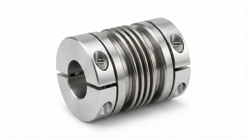
Bellows Coupling
Features metallic bellows construction offering superior torsional rigidity and excellent angular, parallel, and axial misalignment accommodation. Ideal for high-precision encoder feedback systems and servo applications.
Rigid Coupling
Provides solid shaft connection with maximum torque transmission capability and zero misalignment tolerance. Best suited for perfectly aligned shafts requiring absolute torsional rigidity in heavy-duty power transmission applications.
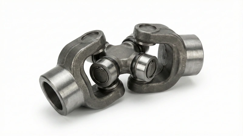
Universal Joint Coupling
Utilizes cross-pin mechanism enabling significant angular misalignment between intersecting shafts. Commonly deployed in automotive drivelines and industrial equipment requiring torque transmission through varying shaft angles during operation.
Flexible Customization Capabilities
Our engineering and manufacturing expertise transforms unique application challenges into precision-crafted coupling solutions tailored to your exact specifications
Shaft Diameter Customization
Accommodate any non-standard shaft dimension from 3mm to 150mm with precision boring and finishing processes. Custom keyway profiles, spline configurations, and set screw positioning ensure perfect fit with your existing equipment without costly shaft modifications or adaptors.
Length & Width Modification
Adjust overall coupling length and width dimensions to fit space-constrained installations or specific center distance requirements. Our machining capabilities enable length adjustments from -20mm to +50mm beyond standard dimensions while maintaining structural integrity and torque capacity specifications.
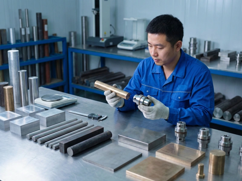
Material Selection Service
Choose from extensive material portfolio including aerospace-grade aluminum alloys, corrosion-resistant stainless steels, high-strength tool steels, and exotic materials like titanium or bronze. Material selection guidance considers operating environment, chemical exposure, temperature extremes, and weight constraints.
High-Torque Engineering
Develop specialized coupling designs for extreme torque applications exceeding standard catalog ratings. Finite element analysis and torque testing validation ensure reliable performance under sustained heavy loads. Custom hub profiles and reinforced construction deliver 2-5x standard torque capacity when required.
Drawing-Based Manufacturing
Submit your technical drawings in any standard format (PDF, DWG, STEP, IGES) and receive precision-manufactured couplings matching exact specifications. Our quality team validates all dimensions against provided drawings with detailed inspection reports documenting compliance before shipment approval.
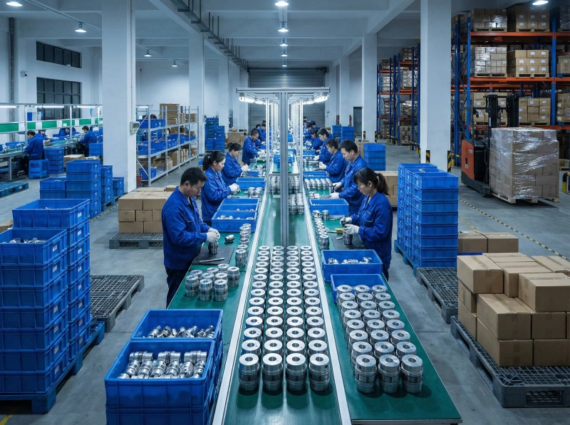
Volume Production Capability
Scale from prototype quantities to high-volume manufacturing runs with consistent quality and competitive pricing. Dedicated production lines handle orders from 10 pieces to 10,000+ units monthly. Volume discounts, vendor-managed inventory, and scheduled delivery programs optimize your supply chain efficiency.
Transform your unique coupling requirements into precision reality
Start Custom ProjectProfessional Coupling Selection Guide
Master the engineering principles behind optimal coupling selection to avoid costly specification errors and ensure maximum equipment reliability
Torque-Based Selection Methodology
Proper coupling selection begins with accurate torque calculation. Multiply nominal motor torque by appropriate service factor (typically 1.5-3.0 depending on load characteristics). Shock loads, frequent starts/stops, and variable speed drives require higher service factors to prevent premature coupling failure.
Selection Formula:
Required Coupling Torque = Motor Torque × Service Factor × Safety Margin (1.25)
Pro Tip: Always specify coupling torque rating at least 25% above calculated requirement to account for unexpected load spikes and provide operational margin for equipment longevity.
Shaft Diameter & Keyway Matching
Measure shaft diameters precisely at coupling mounting location using calipers. Standard keyway dimensions follow DIN 6885 or ISO standards - verify actual keyway width and depth against standards. Coupling bore tolerance typically H7 for standard fits; interference fits require careful heating/cooling installation procedures.
Critical Measurement Checklist:
Speed Range Considerations
Maximum coupling speed depends on outer diameter, material density, and balance quality grade. High-speed applications (>3,000 RPM) require precision-balanced couplings to G2.5 or better. Operating beyond rated speed causes catastrophic failure from centrifugal forces - never exceed manufacturer specifications.
High-Speed Applications (>5,000 RPM)
- Metallic bellows or disc couplings
- Minimum mass and inertia
- Precision dynamic balancing required
- Frequent inspection intervals
Low-Speed Applications (<1,000 RPM)
- Jaw or gear couplings acceptable
- Focus on torque capacity over balance
- Standard balance grades sufficient
- Extended maintenance intervals possible
Rigid vs. Flexible Selection Strategy
Rigid couplings demand precise shaft alignment (typically <0.05mm parallel and <0.1° angular misalignment) but offer maximum torque transmission and zero torsional compliance. Flexible couplings accommodate misalignment and vibration but introduce slight backlash and reduced torsional stiffness affecting system response.
Selection Decision Framework:
Rigid coupling → Maximum power, zero backlash
Flexible coupling → Protect bearings, accommodate thermal expansion
Elastomeric coupling → Shock absorption, electrical isolation
Common Selection Mistakes to Avoid
Most coupling failures stem from improper initial selection rather than manufacturing defects. Understanding these frequent errors prevents costly equipment damage and production downtime.
Undersizing Torque Capacity
Selecting coupling based on motor nameplate rating without service factor multiplier. Results in premature wear, elastomer failure, or complete coupling fracture under normal operating loads.
Ignoring Misalignment Limits
Installing flexible coupling beyond its rated misalignment capacity creates excessive bearing loads, accelerated wear, and vibration. Always verify actual alignment falls within coupling specifications.
Wrong Material for Environment
Specifying standard carbon steel in corrosive environments or elastomer couplings in high-temperature applications. Material incompatibility causes rapid degradation and unexpected failure.
Neglecting Inertia Matching
Using heavy coupling on servo motor reduces system response and positioning accuracy. High-performance motion control requires low-inertia coupling selection matched to motor specifications.
Still uncertain about the optimal coupling for your specific application?
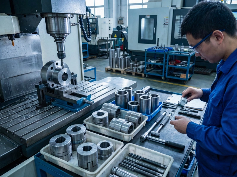
Request Engineering ReviewPrecision Manufacturing Process
Six-stage quality-controlled production workflow ensures every coupling meets exacting specifications for dimensional accuracy, surface finish, and mechanical performance
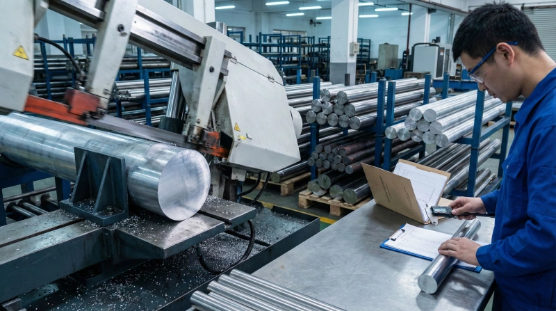
Raw Material Preparation
Premium-grade aluminum alloys, stainless steel, and tool steel billets undergo precision cutting on CNC band saws with ±0.1mm tolerance. Material certification documents verify chemical composition and mechanical properties meet international standards before entering production.
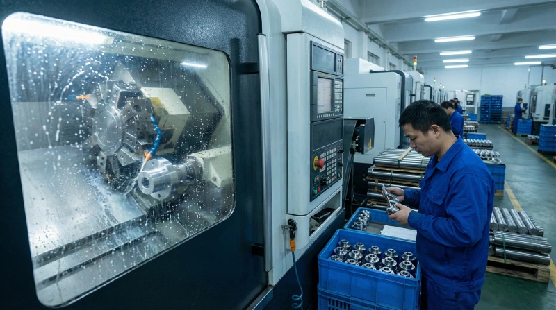
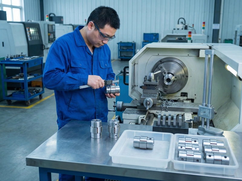
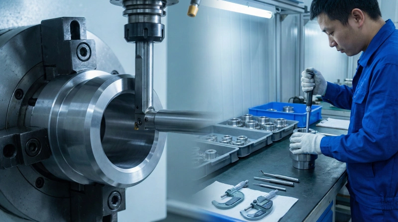
CNC Precision Turning
Multi-axis CNC lathes execute automated machining programs maintaining ±0.01mm dimensional accuracy across all features. Real-time tool wear monitoring and automatic compensation ensure consistent quality throughout production runs of thousands of pieces.
Bore & Chamfer Finishing
Internal bore dimensions machined with precision boring bars achieve H7 tolerance fits for shaft mounting. Chamfer edges deburred to specified radii prevent assembly damage and stress concentrations while maintaining professional appearance and safe handling characteristics.
Dynamic Balance Correction
High-speed balancing machines identify mass distribution irregularities and guide precision material removal to achieve G2.5 balance grade or better. This critical step eliminates vibration sources that would otherwise cause premature bearing failure in high-RPM applications.
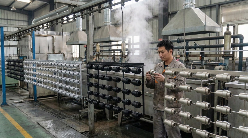
Surface Treatment Application
Anodizing, black oxide, or electroplating processes provide corrosion protection and enhanced surface hardness. Automated treatment lines ensure uniform coating thickness and appearance while maintaining critical dimensions. Optional color coding available for inventory management systems.
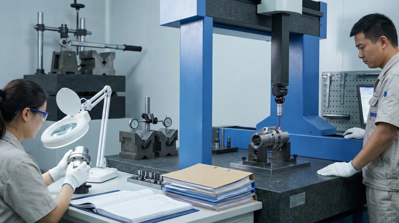
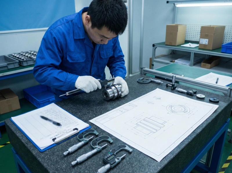
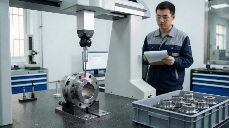
Final Quality Verification
Coordinate measuring machines (CMM) verify all critical dimensions against engineering drawings. Torque capacity testing, concentricity measurement, and visual inspection complete quality assurance protocol. Detailed inspection reports accompany each shipment documenting full compliance.
Experience manufacturing excellence that transforms precision requirements into reliable reality
Schedule Factory TourComprehensive Quality Management System
Multi-stage inspection protocols and advanced metrology equipment guarantee consistent coupling performance that meets or exceeds customer specifications and industry standards
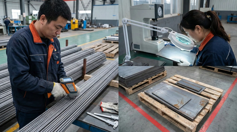
Incoming Material Inspection
Every material batch undergoes spectrometer analysis verifying chemical composition, hardness testing confirming mechanical properties, and surface quality examination detecting defects. Non-conforming materials quarantined immediately preventing inferior components from entering production workflow.
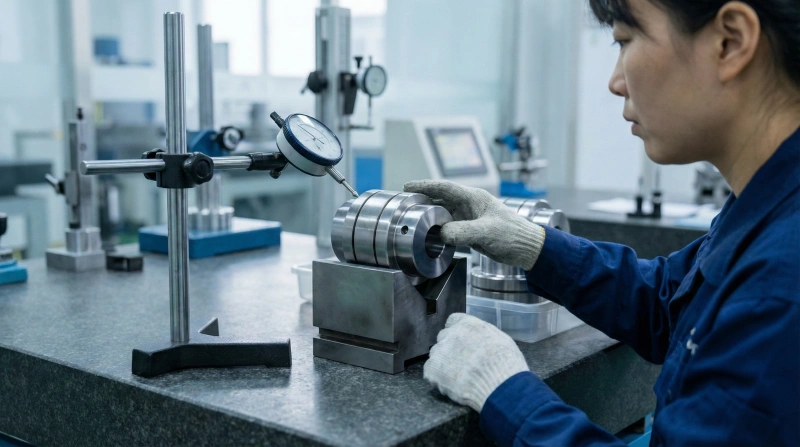
Concentricity Measurement
Precision runout gauges measure radial deviation between bore and outer diameter ensuring perfect concentricity within 0.02mm tolerance. Poor concentricity causes vibration and premature wear - our testing eliminates this failure mode through rigorous measurement protocols on every coupling produced.
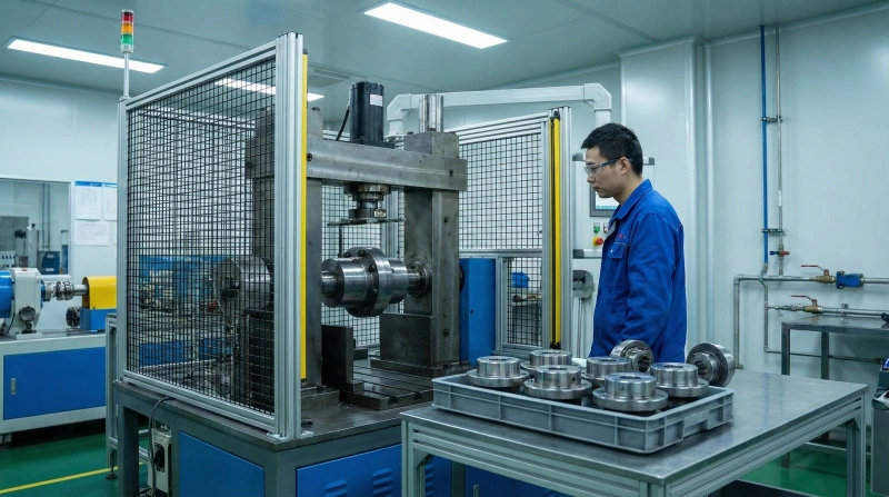
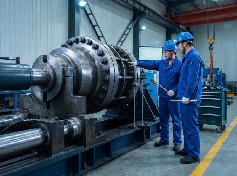
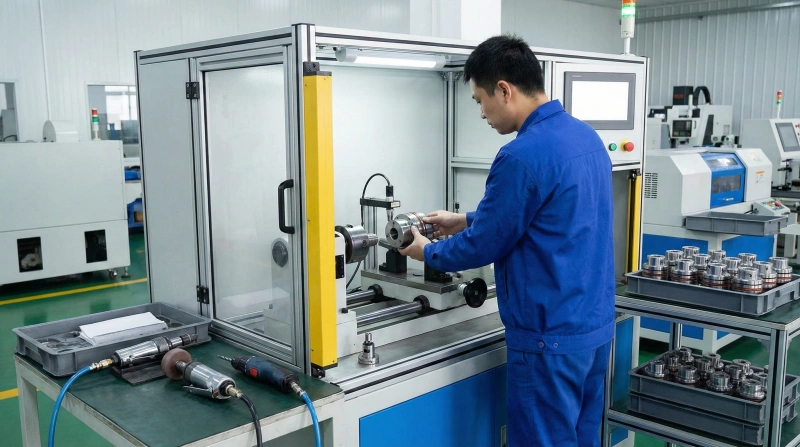
Torque Capacity Testing
Automated torque test stands apply increasing loads verifying coupling withstands rated torque plus 50% safety margin without slippage or permanent deformation. Statistical sampling from each production batch ensures consistent performance characteristics across entire order quantities.
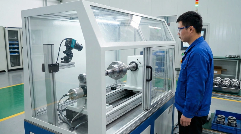
Dynamic Balance Validation
After balance correction, couplings spin at maximum rated speed on precision balancing machines confirming vibration levels meet G2.5 grade specifications. High-speed cameras capture any visible wobble while accelerometers quantify residual imbalance ensuring smooth operation in customer applications.
Multi-Point Dimensional Verification
Coordinate measuring machines (CMM) with 0.001mm resolution verify critical dimensions including bore diameter, keyway dimensions, overall length, and face parallelism. Digital inspection reports document actual measurements against drawing tolerances providing traceability and quality assurance documentation.
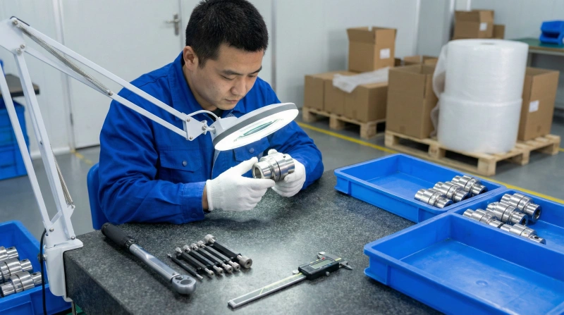
Final Assembly Inspection
Trained quality inspectors perform comprehensive visual and functional checks including surface finish assessment, thread engagement testing, and complete dimensional review. Only couplings passing all criteria receive quality certification and packaging approval for shipment to customers.
Quality Certifications & Standards
ISO 9001:2015
RoHS Compliant
CE Marking
AGMA Standards
Quality assurance documentation available for every order
Request Quality CertificateWhy Leading Manufacturers Choose Our Couplings
Five critical advantages directly address your procurement challenges, transforming coupling-related problems into competitive operational strengths
Precision Manufacturing Eliminates Vibration
Your Challenge: Equipment vibration from poor coupling quality damages bearings, reduces accuracy, and creates maintenance headaches.
Our Solution: ±0.01mm machining tolerance and G2.5 dynamic balancing deliver vibration-free operation that protects expensive motors and extends bearing life by 3-5x industry averages.
Engineering Support Prevents Mismatches
Your Challenge: Non-standard shaft diameters and uncertain specifications lead to ordering wrong couplings and installation delays.
Our Solution: Experienced mechanical engineers review your application requirements, perform torque calculations, and recommend optimal coupling specifications before you commit to purchase orders.
Premium Materials Ensure Longevity
Your Challenge: Low-grade materials cause frequent coupling failures, unexpected downtime, and escalating replacement costs that destroy budgets.
Our Solution: Aerospace-grade aluminum alloys, marine-grade stainless steel, and certified tool steels with material traceability documentation ensure 5+ year service life even in demanding continuous-operation environments.
Reliable Supply Prevents Production Stops
Your Challenge: Unpredictable supplier delivery schedules force production line shutdowns and emergency expediting fees that multiply procurement costs.
Our Solution: Dedicated production capacity, safety stock inventory, and vendor-managed programs guarantee on-time delivery within quoted lead times. 98% on-time delivery rate validated by customer satisfaction metrics.
Quality Systems Guarantee Consistency
Your Challenge: Inconsistent manufacturing tolerances create assembly difficulties, misalignment problems, and unpredictable performance across production batches.
Our Solution: ISO 9001:2015 certified quality management systems with CMM verification, statistical process control, and comprehensive inspection documentation ensure every coupling meets identical specifications regardless of order size or production date.
Transform coupling challenges into operational advantages
Start Your PartnershipFrequently Asked Questions
Expert answers to common coupling selection and procurement questions help you make informed decisions and avoid costly specification mistakes
How do I choose the appropriate coupling type for my application?
Coupling selection depends on five critical parameters: required torque capacity, operating speed range, acceptable misalignment, shaft diameters, and environmental conditions. Start by calculating required torque using motor nameplate rating multiplied by service factor (1.5-3.0 based on load characteristics). For precision motion control requiring zero backlash, specify flexible bellows or disc couplings. General industrial drives with moderate misalignment tolerate jaw or elastomeric couplings effectively. High-torque, perfectly-aligned applications benefit from rigid coupling designs. Our engineering team provides free application review services including torque calculations and coupling recommendations tailored to your specific requirements.
Can you customize shaft bore diameters to match our equipment?
Yes, we specialize in custom bore machining for non-standard shaft dimensions. Our precision boring capabilities accommodate shaft diameters from 3mm to 150mm in both metric and imperial specifications. Custom keyway profiles, spline configurations, D-shaped bores, and set screw positioning available without tooling charges for quantities over 50 pieces. Provide shaft diameter, keyway dimensions (if applicable), and shaft end configuration - we'll machine coupling bores to H7 tolerance ensuring proper fit. Lead time for custom boring typically adds 3-5 days to standard production schedule. CAD drawings or physical shaft samples help ensure perfect dimensional matching on first order.
What is your minimum order quantity for standard couplings?
Minimum order quantity varies by coupling type and customization level. Standard catalog items available in quantities as low as 10 pieces for prototype development or equipment repair applications. Custom bore diameters or special material requests typically require 50 piece minimum to offset setup costs economically. Volume pricing tiers activate at 100, 500, and 1,000+ piece quantities offering progressive discounts up to 35% off unit pricing. For large ongoing requirements, we offer vendor-managed inventory programs with scheduled deliveries and blanket purchase orders eliminating minimum order constraints. Sample quantities (1-5 pieces) available for testing and validation at standard pricing plus shipping costs.
Do you provide 3D CAD models and technical drawings?
Complete 3D CAD models available in multiple formats including STEP, IGES, Parasolid, and SolidWorks native files for all standard coupling products. Download models directly from product pages or request via email for immediate delivery. 2D technical drawings in PDF and DWG formats include all critical dimensions, tolerances, material specifications, and torque ratings. For custom coupling designs, we provide approval drawings showing your specific modifications before production begins. CAD models accurately represent as-manufactured dimensions enabling interference checking in your assembly designs. Mass properties and moment of inertia values included for dynamic analysis and servo motor sizing calculations.
What are typical lead times from order to delivery?
Standard catalog couplings with in-stock inventory ship within 2-3 business days after order confirmation and payment processing. Custom bore or special material couplings require 2-3 weeks production time depending on quantity and complexity. High-volume orders (500+ pieces) typically need 3-4 weeks for manufacturing and quality inspection completion. Rush production available for urgent requirements with 5-7 day expedited manufacturing at 20% premium charge. International shipping adds 5-10 days via air freight or 4-6 weeks for ocean container shipments. We provide proactive order status updates and tracking information throughout production and shipping process. Lead time commitments confirmed at quotation stage based on current production capacity and material availability.
Have a question not covered here?
Contact Technical SupportRequest Your Custom Coupling Quote
Complete the form with your specific requirements and our engineering team will respond within 24 hours with detailed quotation, technical recommendations, and delivery timeline. Every inquiry receives professional attention from experienced coupling specialists.
24-Hour Response
Fast quotation turnaround for all inquiries
Engineering Support
Expert technical consultation included
Free CAD Files
3D models and drawings provided
Quality Guarantee
ISO certified manufacturing processes